Cold Removal Process of Components on Wireless Devices Dramatically Increases Yields
By Bob Wettermann, BEST Inc
Handheld consumer and commercial electronics that use some form of wireless communication (e.g. cell phones, tablets, wireless radios, tablet computers, etc.) have specific challenges when they are brought into repair depots for disposition. When the printed circuit boards inside such electronics have underfill protecting the most sensitive components’ solder connections, the removal and replacement of these components during the repair process has low yields and high costs. While the underfill allows the devices to survive being dropped from several meters or more, these underfilled circuit boards present serious challenges when it comes to swapping out components. Industry standard processes involving heat are used to remove these components. The heat cycle “softens” the underfill causing it to flow thereby pushing solder into locations where solder shorts, solder anomalies and other board defects occur. In addition to the low yields caused by these soldering anomalies the high skill level manual process makes many of these repairs beyond economic repair.
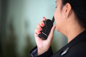
Figure 1- Wireless Communication System for Retail-Courtesy of Motorola
The Problem
There are numerous challenges associated with the rework of PCBs with underfilled components including but not limited to :
- The economics of underfill rework are not cost-effective. Most of the current processes are low yielding and require long processing times for skilled electronics repair technicians
- The so called class of “non-reworkable” underfills preferred by the OEMS for a variety of their performance characteristics, are challenging to rework using standard PCB rework processes and tools
- Damaging the PCB is a real risk factor as it reduces the assembly reliability because of the underfill rework process
- The use of aggressive chemicals to remove the underfill is frowned upon as it is generally unknown how these chemical aids impact electronic components and printed circuit boards
- Many underfills, when subjected to the desoldering temperatures found in PCB rework can displace solder joints and components resulting in defects
The common heat-based methods for removing a component from an underfilled PCB can cause yield problems. The most common methods for component removal use various tools along with heat, chemicals and lasers which can remove the materials.
When using a standard heat-based component removal process such as infrared energy or hot air a component can be removed on PCBs not containing underfill. However, since the underfill provides a strong adhesive force which holds the component to the PCB, it is difficult to break this bond and remove the component. Either specialty rework machines or specialty custom nozzles are required to break this bond and remove the component. This adhesion can be broken by the use of specialty cutting tools, hot knives or sharp-bladed tools. Too much pressure applied to break this bond or the use of an improper technique may damage the printed circuit board. In addition, once the component is broken free of the underfill, this very tacky material needs to be cleaned from the board location, requiring a high level of dexterity and patience on the part of the repair technician. Proper site preparation is required in order to place and solder the replacement BGA. No matter how experienced and careful the technician is, the board may be damaged beyond an economic point of repair by improper site cleaning.
In addition to the use of a heat source to break the component free from the grip of the underfill, specially formulated solvents may be used to surround the component to loosen up or soften the underfill. This results in a potential liability as it may be unknown how the aggressive chemicals interact with the components or PCB. In addition, the use of these caustic chemicals cause challenges in their disposal and operator exposure.
Lastly, focused laser energy may be directed at the component to be removed in order to ablate or remove material from the radiated source. This process involves careful laser processing and source selection as the wavelength of the laser needs to be tuned to multiple material absorption spectra to ablate the material. In addition, the depth of the laser needs to be carefully controlled in order to not damage neighboring components or the PCB. Not only is the laser ablation approach capital-intensive in terms of investing in the laser but a high degree of operational sophistication is necessary.
A New Solution- a Refined Cold Milling Process
An idea which has been developed further recently is precision milling for the complete removal of the component from an underfilled printed circuit board. This is a “cold” process which does not heat the underfill or the solder for component removal instead relying on a precisely-controlled milling tool to cut away the component body, the solder attaching the component to the PCB as well as the underfill. This removes the component completely leaving only a small remnant of the solder from the component on the board. After this process the slight remainder of the solder will be cleaned from the pads or alternatively the component can be placed back onto the remnant solder and be soldered into position. This process eliminates the possibility of solder being pushed around by the softened underfill at elevated temperature which can cause defects.
The newly commercially developed, dedicated purpose precision milling machinery simplifies the process of component removal via this “cold” removal milling process. This machine is outfitted with modern controls and is designed for applications where heat is a yield detractor to the PCB rework and repair process.
The machine features several advances including but not limited to:
- Rework software which eliminates the need to have an experienced CNC programmer/operator run the machine as the dimensions of the component generate the milling pattern. After being programmed the machine operator can run the machine without having to program milling patterns.
- Metal and other board shavings are vacuumed through the cutting tool collet while the process is going on thereby protecting the board from any metallic debris which may cause functional defects.
- Laser-based measuring allows the elements of the component to be removed within a few thousands of an inch of the PCB. This is done by the machine and increases the process yield.
- Vacuum-based board holding and support is used in order insure the highest yields by making sure the milling is done as coplanar to the PCB surface as possible.
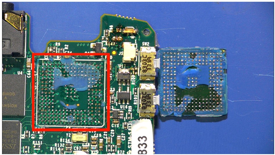
Figure 2-Underfilled BGA rework location for retail communication system
A Case Study
A handheld retail communications PCB (Figure 1) had underfill applied at a variety of component locations including the main processor location (red outline Figure 2). The adhesive properties of the non-reworkable underfill caused the underlying component pads to become lifted off the board during standard hot air removal (Figure 3). Removing the remnant solder and underfill from the BGA location resulted in numerous damaged pads. The repair of the damaged pads, shown via their copper color in Figure 3, made the repair time consuming and BER (beyond economic repair).
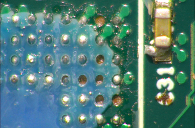
Figure 3 -Lifted pads after removal of underfilled BGA
After consultation with the OEM, more samples and further process development yielded a cold removal process using a commercially available precision milling system. After two gross depth cuts and two refined milling profiles, the component was removed with 2.5 mils of solder remaining on the pads (Figure 4). The milling process resulted in no pads being lifted. In addition, this semi-automated process took some of the “art” out of the rework process thereby improving the yield as well as improving the throughput. The component removal time of 14 minutes added 7% to the cost of the rework service. The replacement component was placed directly onto the milled surfaces without further site preparation using a paste flux dipping process. After component placement the BGA had replacement underfill applied.
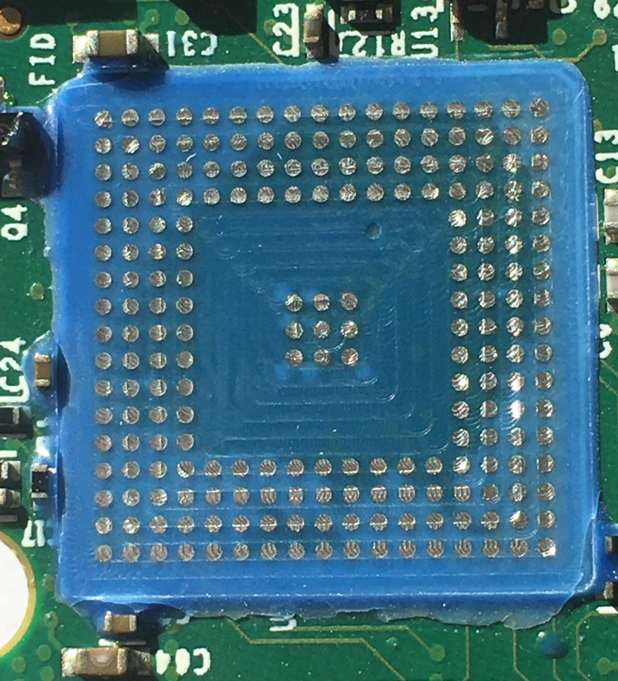
Figure 4- Cold component removal process result
The PCB "cold" component removal processes eliminating the detrimental effects of heat which has improved the rework yields. This programmable automated machinery makes for a repeatable process which reduces the reliance on highly skilled repair technicians while at the same time resulting in high rework yields time providing excellent results.
 Bob Wettermann
Bob Wettermann has been engineering PCB rework and repair projects for 22 years. He is an IPC certified SME and has written over 60 articles on PCB assembly and PCB rework and repair. In addition, he has championed the industry acceptance of new PCB rework and repair methods as an IPC technical committee representative. Bob is a BSEE from the University of Illinois and is the principal of BEST Inc. in Chicago.